ALU 1.0 mods & pics
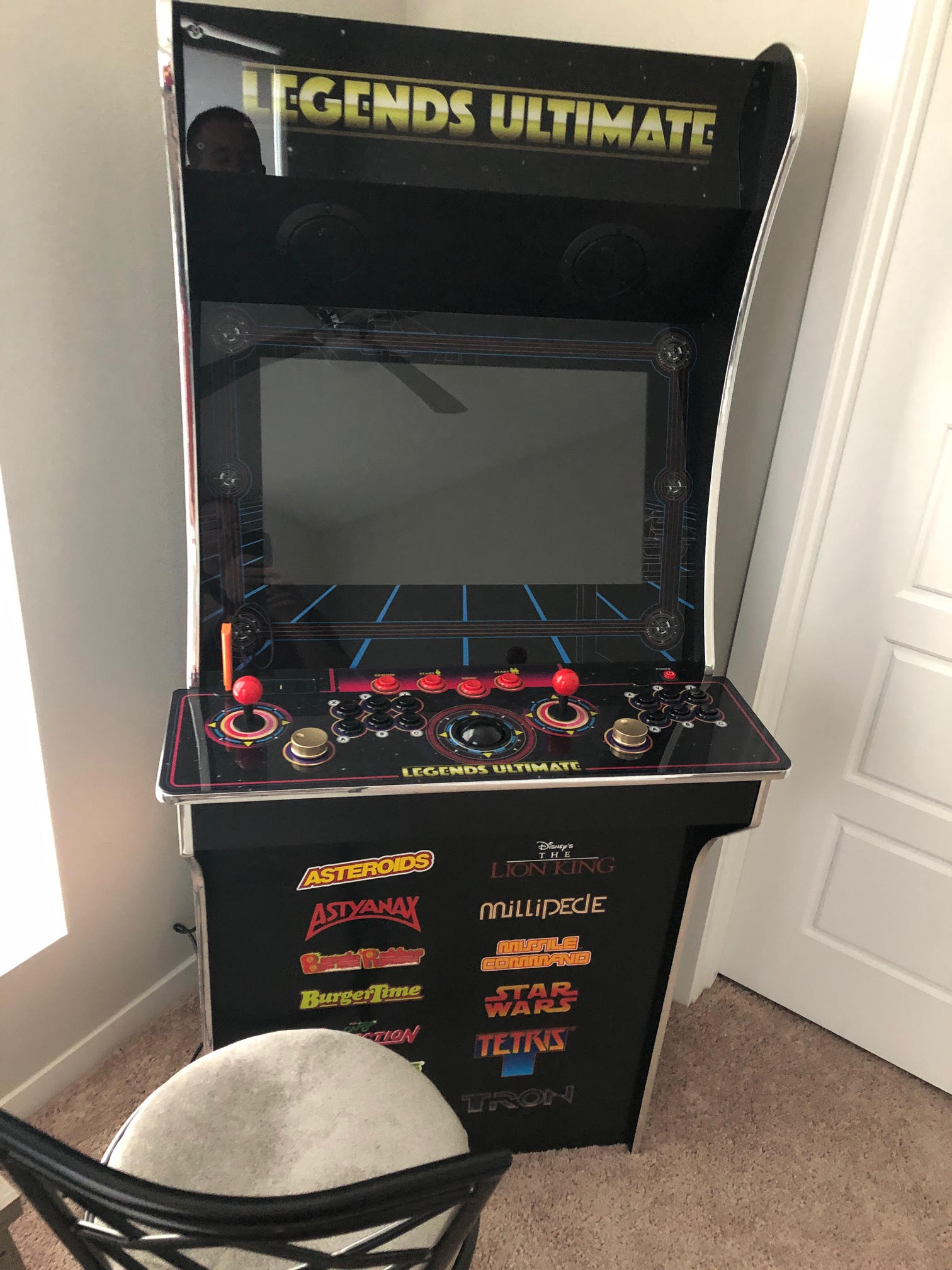
I’ve done a number of mods on my AtGames ALU 1.0. They have happened in four separate stages. Since I’ve been asked quite a few times for links, here’s what I’ve done, and the parts I’ve used. Prior to doing anything, here’s what my ALU 1.0 looked like:
STAGE 1
Replaced red joystick ball tops with black bat tops. Changed the restrictor gate from 4-way to 8-way. Upgraded joystick springs to 4#. Changed out the four system menu buttons with customized white buttons for P1 and P2, with basic white for Menu and Rewind. Installed Sheldon’s shim kit to the trackball as a preventative measure.
Now, some notes. Replacing the joystick toppers is incredibly easy, so that was a plus. Same for restrictor gates. The joystick springs were a little more problematic. Those damn C-clips can kiss my … sorry. I’ll just advise anyone who does this procedure to NOT do it over a shag rug. Trust me on this one. The cool P1 and P2 buttons? Don’t do it, especially if you have nieces & nephews who like playing the game so much that the lower half of the P1 button wore off. Half a little dude on the button? Kinda creepy. The shim kit? It comes with detailed, illustrated instructions on what to do. It was a piece of cake.
Parts for this stage: joystick bat tops, restrictor gates, joystick springs 4#, customized P1 and P2 buttons, regular blank white buttons, shim kit.
STAGE 2
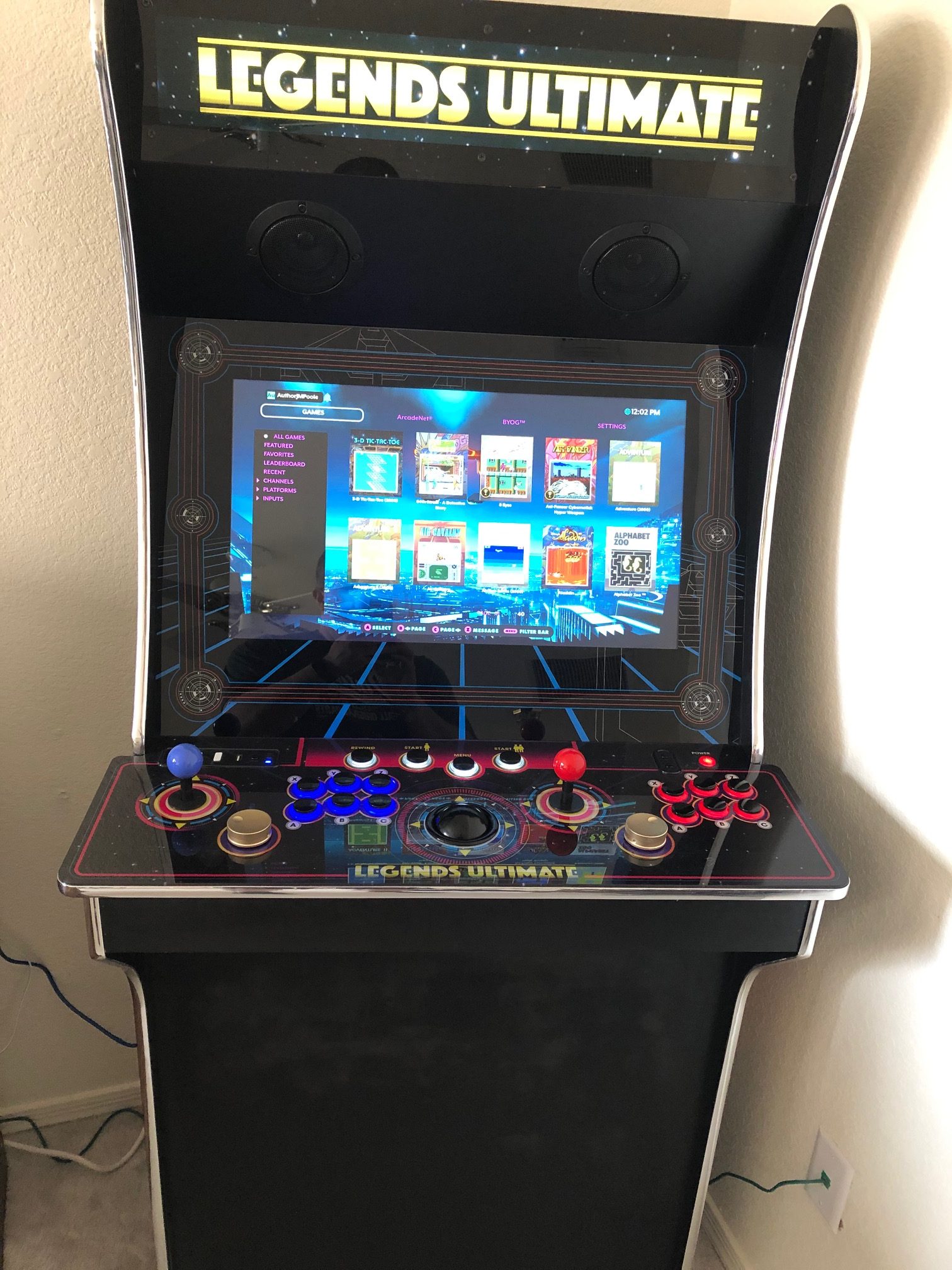
Decided it was time to figure out how to make those eclipse LED buttons work. I’ve seen them on other machines, and have really enjoyed how they look. So, I ordered 16: 6 blue, 6 red, and 4 white. My reasoning? P1 will get blue, because the HDMI input indicator (located on the left side) is blue, and the power button on the right is red, so P2 gets red. Then, all four system buttons will be replaced with white. Also added “Zippy 20G Switch”, which is an optional increase of $0.20, per eclipse button. I found that I really enjoy the resistance of the button and how it feels when pressed. Additionally, I discovered I was NOT a fan of the bat tops, so replaced them with corresponding colored ball tops.
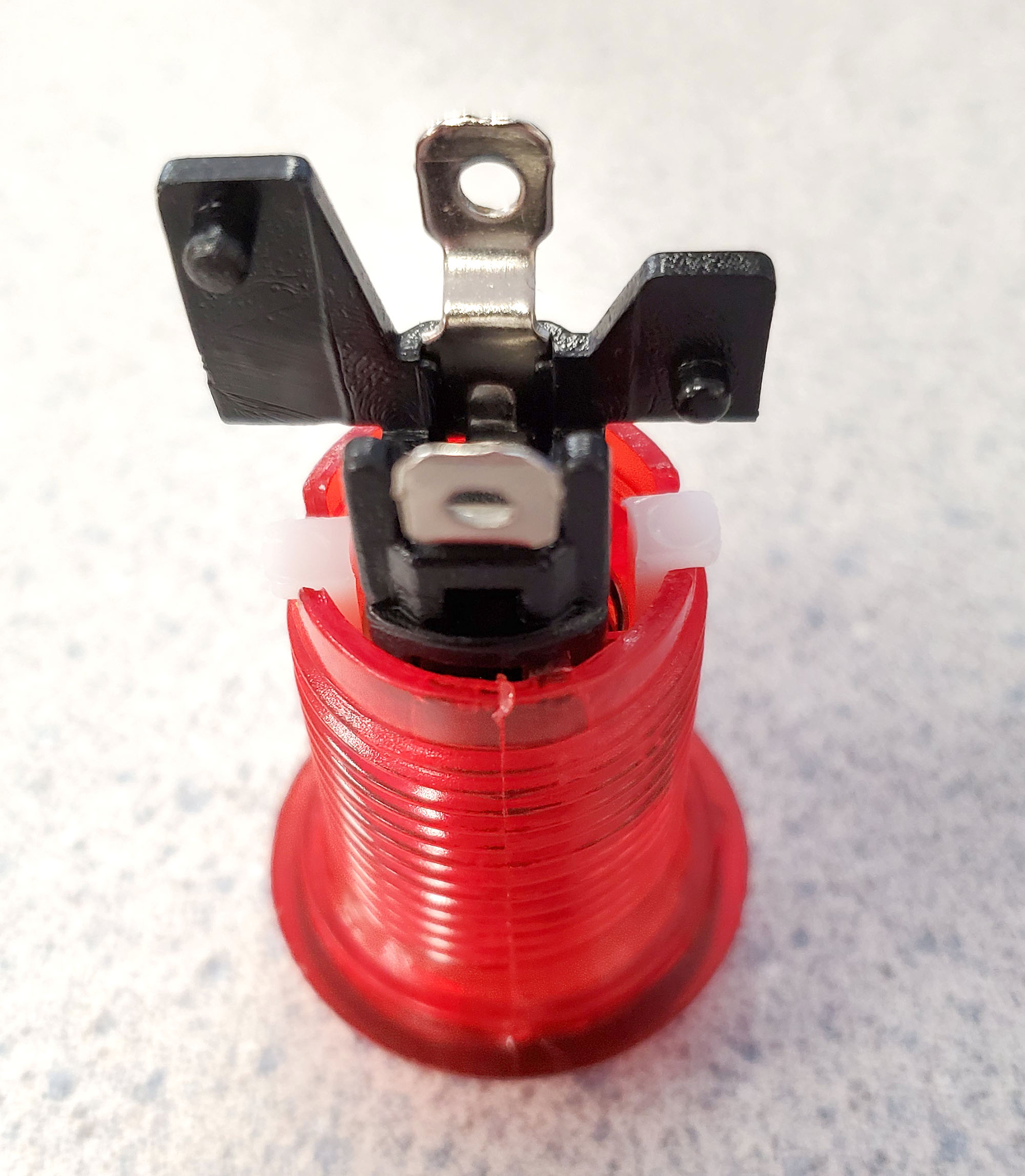
Notes: for this stage, once again, the ball tops swapped out very easily. No issues there. The one issue I did run into was the switch for the eclipse button, It has to be sitting correctly on the plunger, or else the flippin’ thing will pop right off. Thought for certain I had shoddy parts, and wrote to the people at T-Molding to complain. They very patiently explained to me I had the setup wrong (Doh!), and provided a pic of what the correctly inserted switch looks like. Swallowed my pride and ended up apologizing. 🙂 Oh, for the record, this is what the (correctly) inserted switch & plunger look like.
Parts for this stage: Blue eclipse buttons, red eclipse buttons, white eclipse buttons, LED wiring harness, joystick ball tops.
STAGE 3
This stage had me replacing the stock speakers with something more powerful. Plus, I was told where to find speakers with blue LED built inside. Win/win, right? Well, issues arose. Since this stage had multiple parts, and I actually took pics throughout, I’ll break it up. First, I’ll show you what I used.
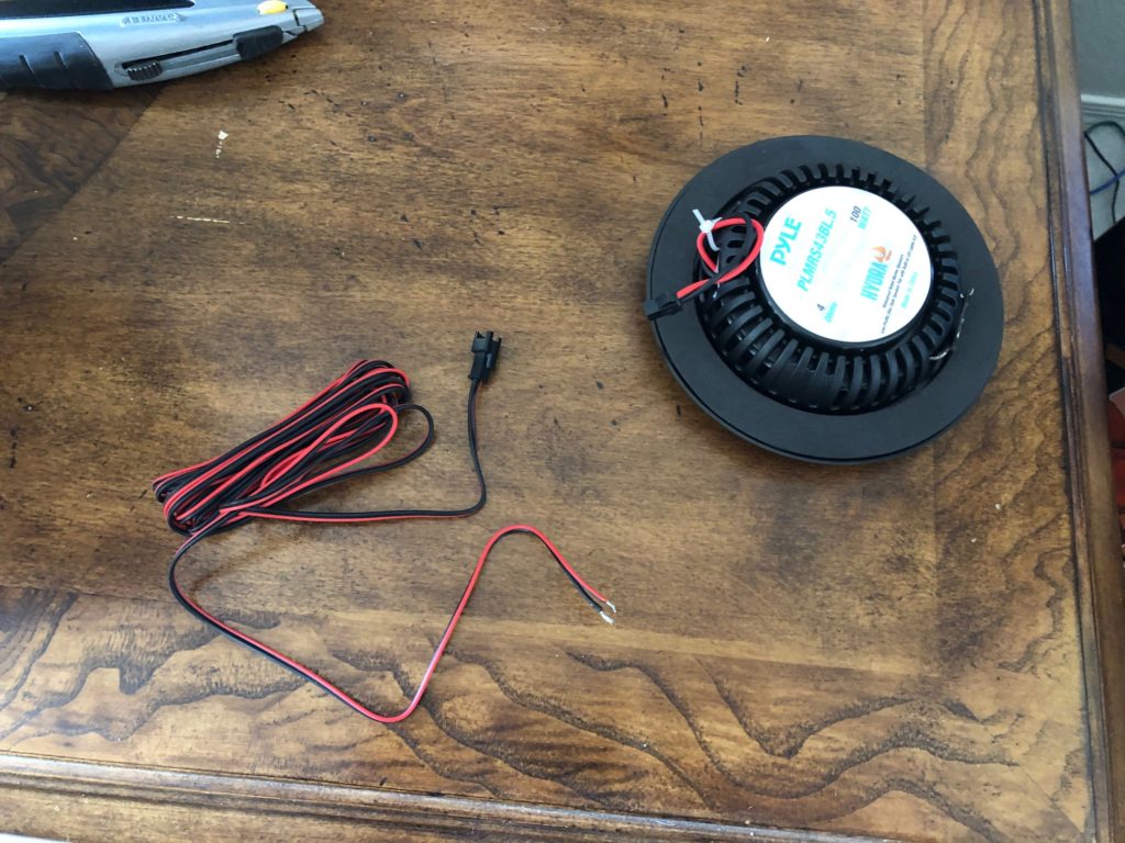
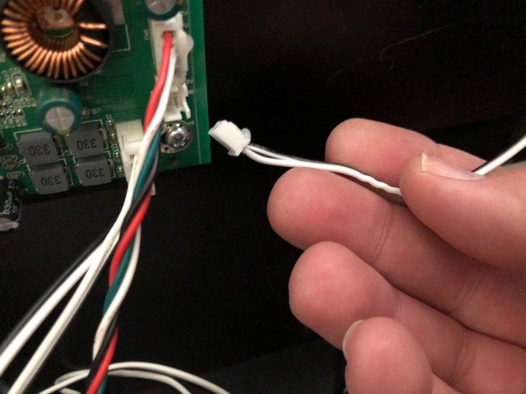
First step, inspecting speaker and the LED hook-up wire. The question I had was, could I use the LED wiring harness from my eclipse buttons to power these things?
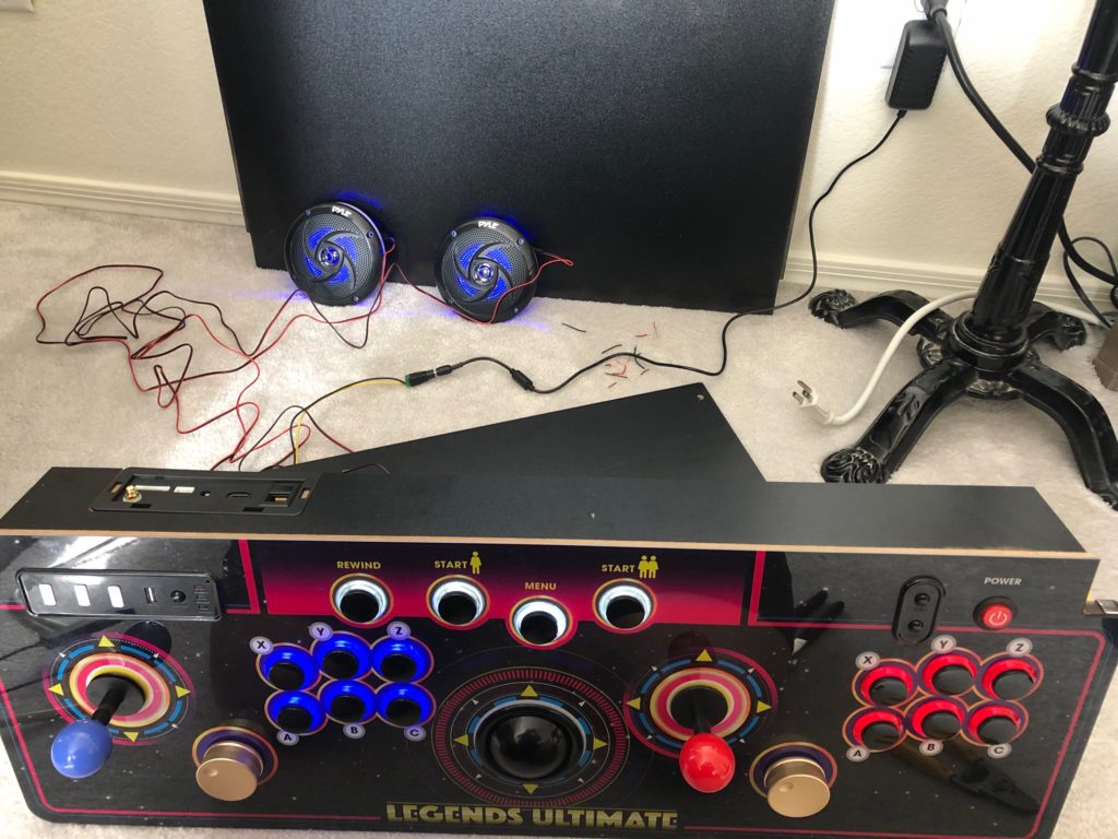
Proof of concept! Yes, I could!
A close-up of the speaker’s LED connection tapping into the eclipse button wiring harness.
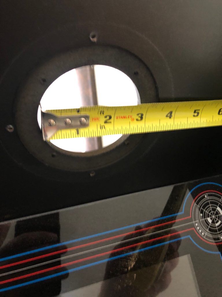
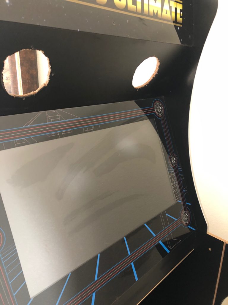
This is where I hit a snag. I will say I was warned about this. The hole, once vacated by the stock speaker, is too small to fit the 4″ speaker. Do you see that recessed smaller ring around the hole, about an inch thick? Either you’ll have to get out the tools, or a Dremel, if you have one, or find smaller speakers. As for me, I really like these things, so it was time to get messy. 🙂
I win! Properly enlarged holes. Man, what a mess I made. That’s what vacuums are for, right?
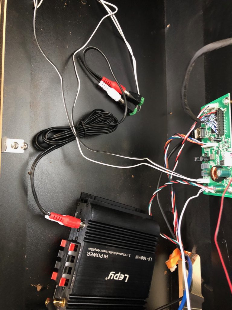
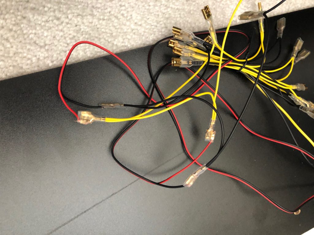
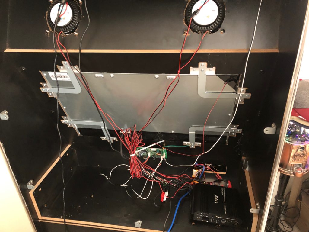
With the speakers FINALLY installed, it was time to hook up the amplifier. You can see the white and black speaker cables coming from the board. Those were clipped from the original speaker and then each set of wires was topped with one of the RCA adapters. Then, take your RCA speaker cables and connect one end to the board’s wires and the other to the amp. Finally, grab the handy-dandy included speaker wires and attach the speakers to the amp.
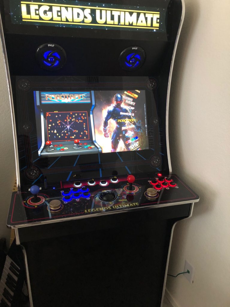
It was time to put everything back together. Here’s the finished result! And, I’d like to add, my wife came around the corner, after telling me I was making a helluva lot of noise, to say, “The speakers light up? How cool!”
Parts for this stage: Speakers, amp, cable adapters (speaker wire to RCA), RCA cables.
Stage 4
My BitPixel finally arrived! AtGames knocked it out of the park with this one. I had the thing up & running in less than 5 minutes. The challenge here was to figure out how to run the USB cord for it, since it needed a port and my cab is a 1.0, which meant no internal USB ports for me.

This is within the first five minutes of unboxing the BitPixel. Wanted to see if I could get it to work. After all, many people have stated that there had been problems, so I wanted to get it working before I worked on hiding the wires.
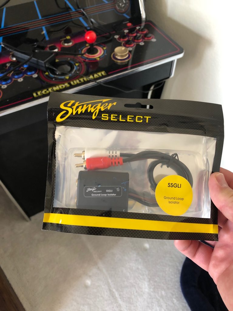
As long as I was at it, I decided to see about removing the soft hum I had after upgrading my speakers. This isolator was recommended, so let’s see how it works.
Inserted the isolator in between the speakers and the amp. Fairly straightforward. Was also advised to ground the unit, so…
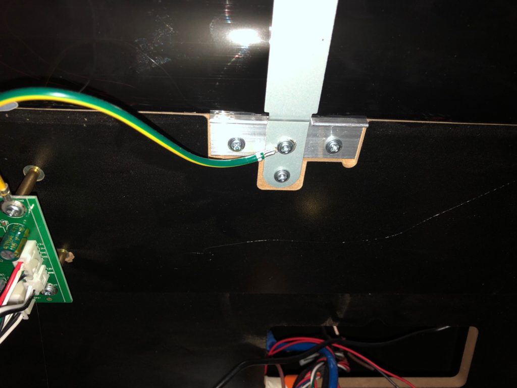
On my ALU 1.0, I found the “grounding plate” and grounded the isolator here.
Also, as long as I had the back off, I unplugged the light bar that was formerly used to light up the marquee. After all, I certainly don’t need it now!
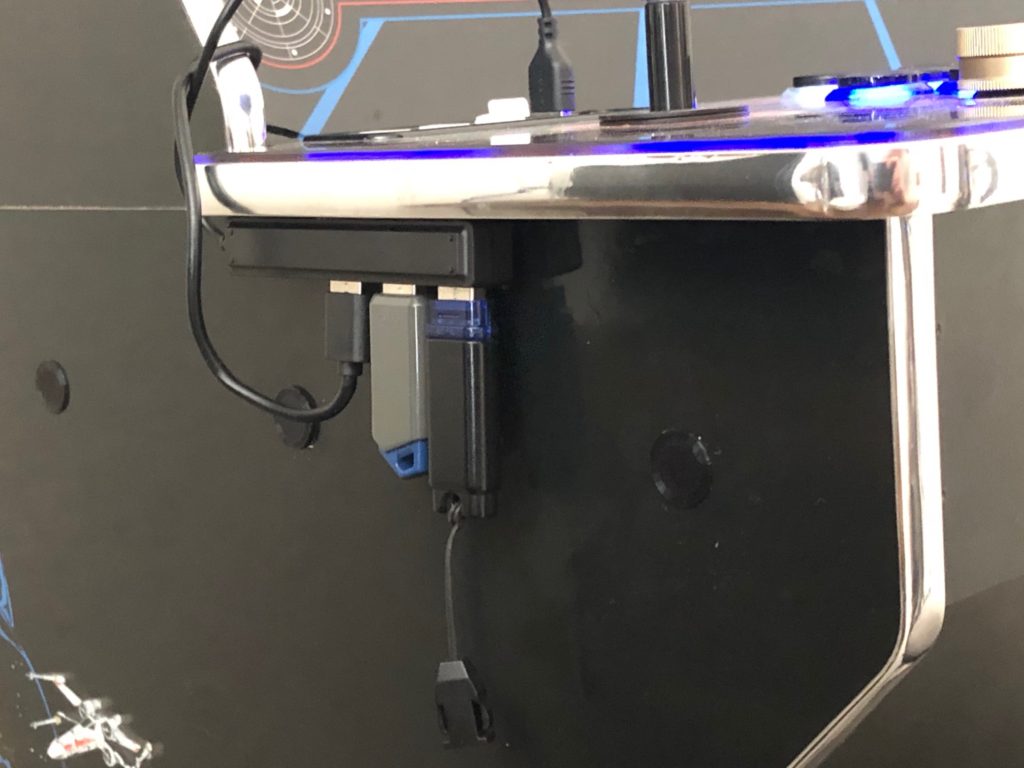
What to do with the wires… well, I definitely needed the hub. That wasn’t negotiable. So, I saw someone else do this. Apply some handy-dandy velcro patches and voila! Tucked out of the way. The BP’s cord is coming up, between the cabinet and the CP.
And finally, the end result. BitPixel is installed, the hum on the speakers is gone, and the cords are as tucked away as I’m going to make them. All power cables are sitting inside the base of the cabinet, plugged into a surge protector, and that surge protector is plugged into an Alexa-enabled wifi plug. All it takes is to tell her to turn on my arcade!
Parts used for this stage: BitPixel, ground loop isolator, non-powered USB hub